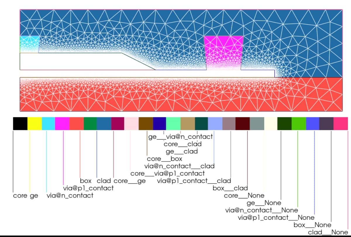
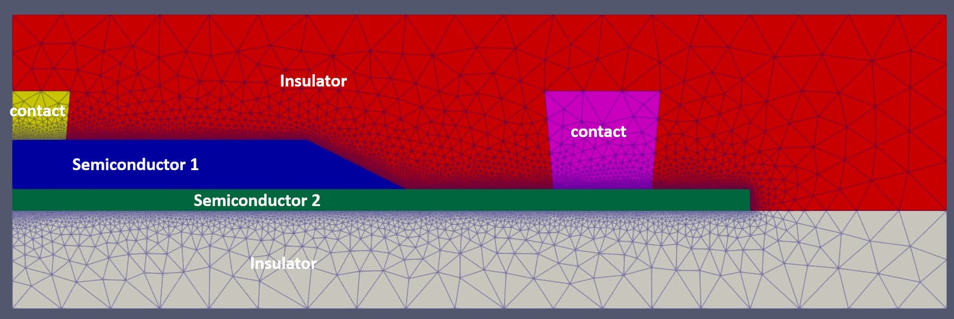
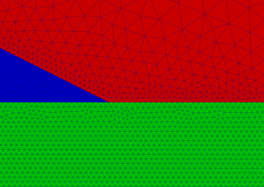
I’m simulating a geometry involving multiple regions like so (actually this is the example I am polishing for this issue, it creates the simulation from gdsfactory layouts and does some nice moment distribution processing for the doping profiles, but I digress ):
I setup Potential and Continuity equations similar to the diode examples.
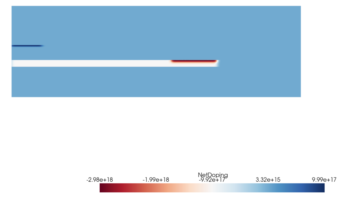
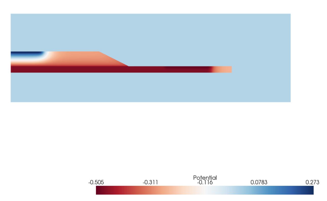
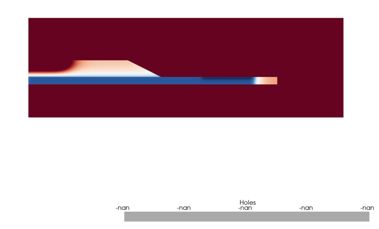
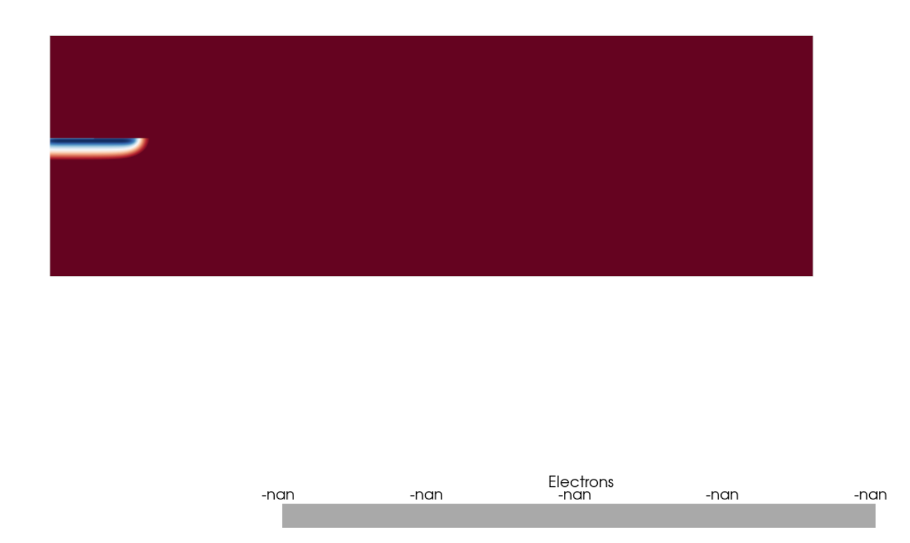
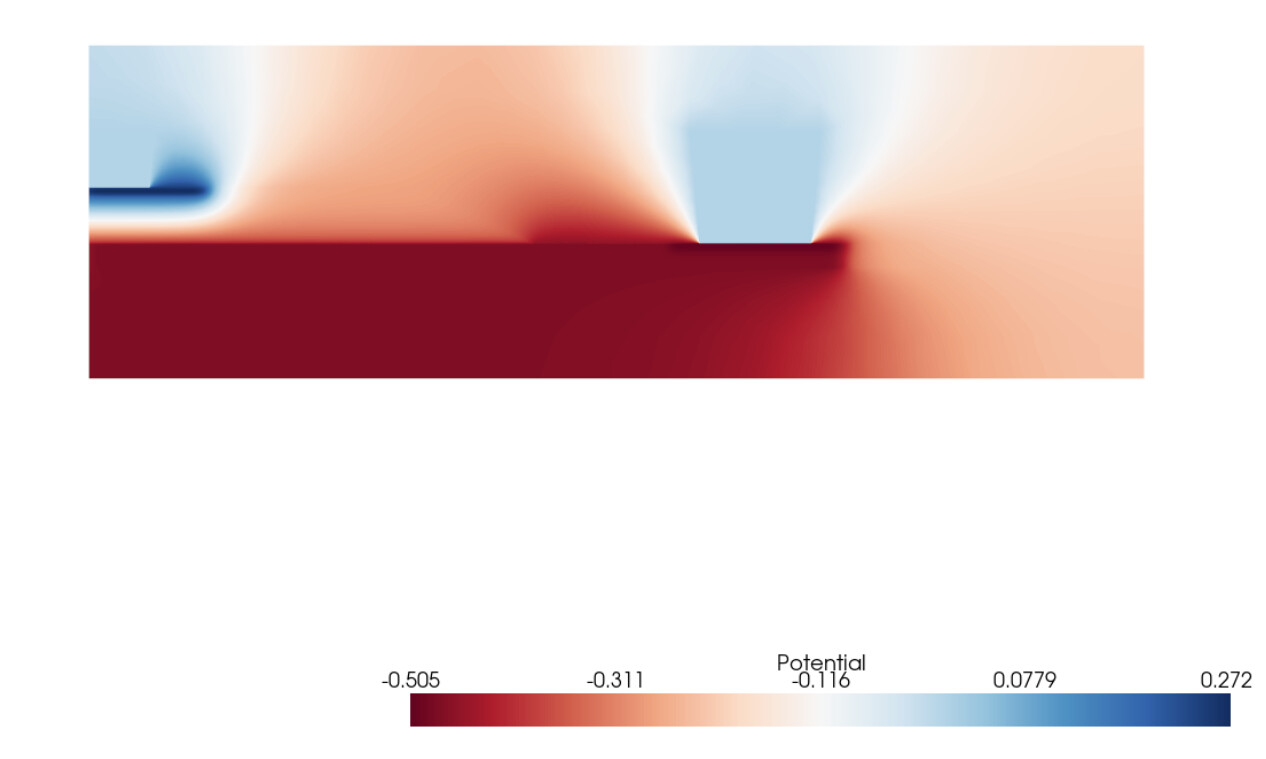
If I only include semiconducting regions (where I define potential, carrier continuity, and their interfaces), then the solve goes well and I get something that I can work with:
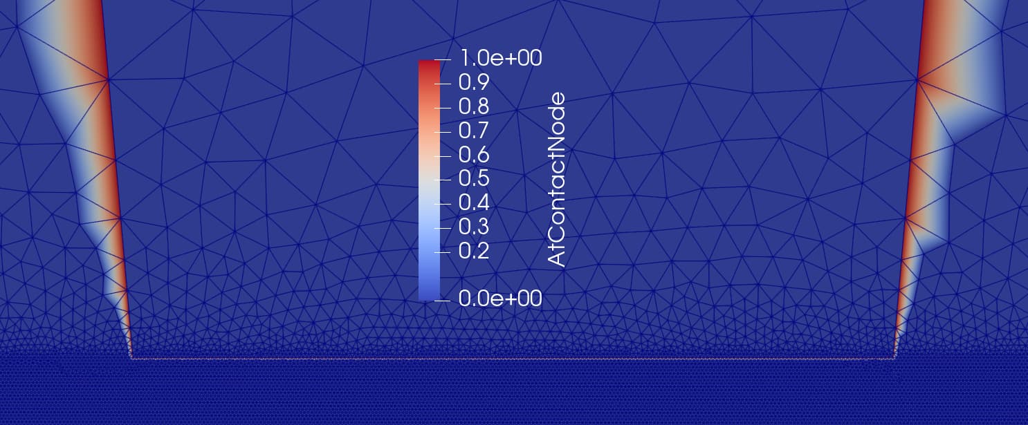
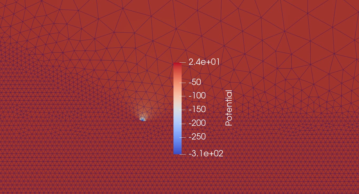
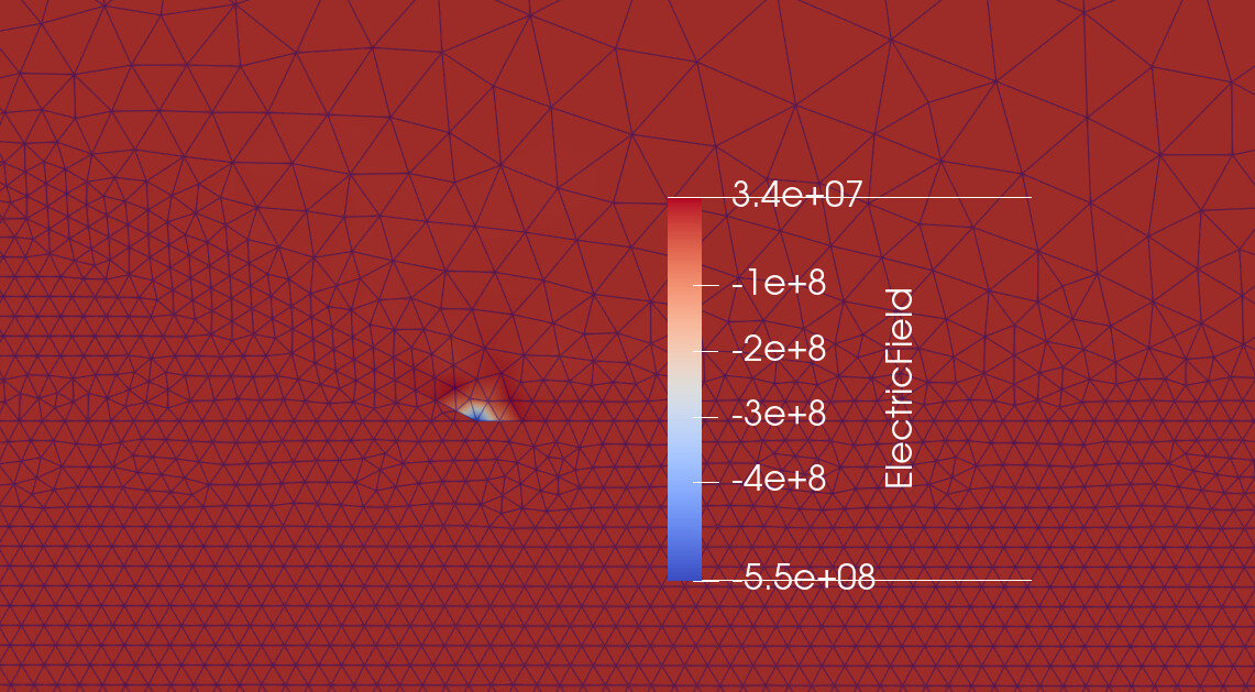
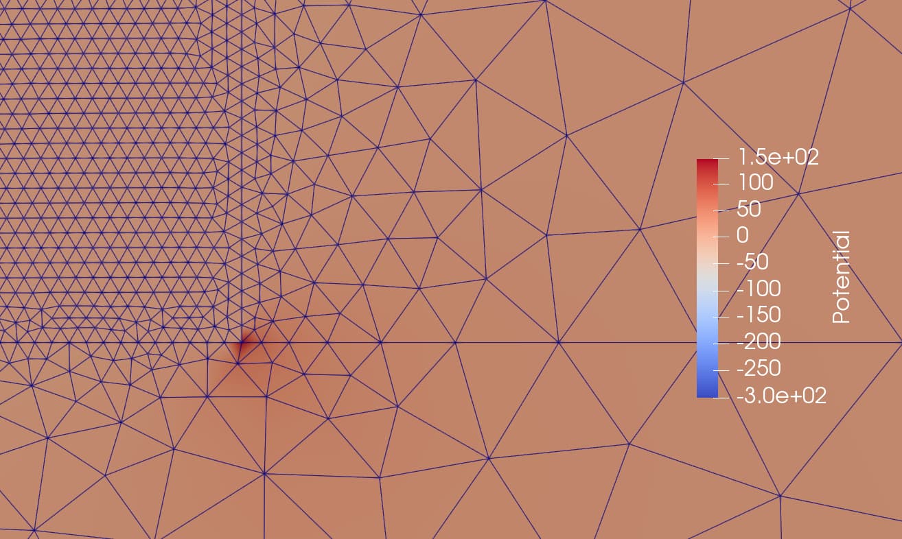
However, if I also add potential models to the insulating regions outside the semiconductors (where I only model potential, and potential continuity at the interface), my simulation does not converge. Inspecting a partial result, I can clearly see the potential/electric field blow up at a specific node:
Physical group name box has 0 Tetrahedra.
Physical group name box has 9994 Triangles.
Physical group name box has 15766 Lines.
Physical group name box has 5773 Points.
Physical group name box___None has 0 Tetrahedra.
Physical group name box___None has 0 Triangles.
Physical group name box___None has 34 Lines.
Physical group name box___None has 35 Points.
Physical group name box___clad has 0 Tetrahedra.
Physical group name box___clad has 0 Triangles.
Physical group name box___clad has 15 Lines.
Physical group name box___clad has 16 Points.
Physical group name clad has 0 Tetrahedra.
Physical group name clad has 11676 Triangles.
Physical group name clad has 18185 Lines.
Physical group name clad has 6510 Points.
Physical group name clad___None has 0 Tetrahedra.
Physical group name clad___None has 0 Triangles.
Physical group name clad___None has 25 Lines.
Physical group name clad___None has 26 Points.
Physical group name core has 0 Tetrahedra.
Physical group name core has 154737 Triangles.
Physical group name core has 233651 Lines.
Physical group name core has 78915 Points.
Physical group name core___None has 0 Tetrahedra.
Physical group name core___None has 0 Triangles.
Physical group name core___None has 44 Lines.
Physical group name core___None has 45 Points.
Physical group name core___box has 0 Tetrahedra.
Physical group name core___box has 0 Triangles.
Physical group name core___box has 1501 Lines.
Physical group name core___box has 1502 Points.
Physical group name core___clad has 0 Tetrahedra.
Physical group name core___clad has 0 Triangles.
Physical group name core___clad has 544 Lines.
Physical group name core___clad has 546 Points.
Physical group name core___ge has 0 Tetrahedra.
Physical group name core___ge has 0 Triangles.
Physical group name core___ge has 801 Lines.
Physical group name core___ge has 802 Points.
Physical group name core___via@p1_contact has 0 Tetrahedra.
Physical group name core___via@p1_contact has 0 Triangles.
Physical group name core___via@p1_contact has 201 Lines.
Physical group name core___via@p1_contact has 202 Points.
Physical group name ge has 0 Tetrahedra.
Physical group name ge has 162926 Triangles.
Physical group name ge has 245252 Lines.
Physical group name ge has 82327 Points.
Physical group name ge___None has 0 Tetrahedra.
Physical group name ge___None has 0 Triangles.
Physical group name ge___None has 100 Lines.
Physical group name ge___None has 101 Points.
Physical group name ge___clad has 0 Tetrahedra.
Physical group name ge___clad has 0 Triangles.
Physical group name ge___clad has 716 Lines.
Physical group name ge___clad has 717 Points.
Physical group name ge___via@n_contact has 0 Tetrahedra.
Physical group name ge___via@n_contact has 0 Triangles.
Physical group name ge___via@n_contact has 109 Lines.
Physical group name ge___via@n_contact has 110 Points.
Physical group name via@n_contact has 0 Tetrahedra.
Physical group name via@n_contact has 1009 Triangles.
Physical group name via@n_contact has 1580 Lines.
Physical group name via@n_contact has 572 Points.
Physical group name via@n_contact___None has 0 Tetrahedra.
Physical group name via@n_contact___None has 0 Triangles.
Physical group name via@n_contact___None has 11 Lines.
Physical group name via@n_contact___None has 12 Points.
Physical group name via@n_contact___clad has 0 Tetrahedra.
Physical group name via@n_contact___clad has 0 Triangles.
Physical group name via@n_contact___clad has 13 Lines.
Physical group name via@n_contact___clad has 14 Points.
Physical group name via@p1_contact has 0 Tetrahedra.
Physical group name via@p1_contact has 1952 Triangles.
Physical group name via@p1_contact has 3043 Lines.
Physical group name via@p1_contact has 1092 Points.
Physical group name via@p1_contact___clad has 0 Tetrahedra.
Physical group name via@p1_contact___clad has 0 Triangles.
Physical group name via@p1_contact___clad has 29 Lines.
Physical group name via@p1_contact___clad has 30 Points.
Device temp_device has 171255 coordinates with max index 171255
Region box has 5773 nodes.
Region clad has 6510 nodes.
Region core has 78915 nodes.
Region ge has 82327 nodes.
Region via@n_contact has 572 nodes.
Region via@p1_contact has 1092 nodes.
Contact core___via@p1_contact in region core with 202 nodes
Contact ge___via@n_contact in region ge with 110 nodes
Adding interface box___clad with 16, 16 nodes
Warning, interface "box___clad" shares a node with interface "core___box"
Adding interface core___box with 1502, 1502 nodes
Warning, contact "core___via@p1_contact" shares a node with interface "core___clad" (repeated 1 times)
Warning, interface "core___box" shares a node with interface "core___clad"
Adding interface core___clad with 546, 546 nodes
Warning, interface "core___clad" shares a node with interface "core___ge"
Adding interface core___ge with 802, 802 nodes
Warning, contact "ge___via@n_contact" shares a node with interface "ge___clad"
Warning, interface "core___clad" shares a node with interface "ge___clad"
Adding interface ge___clad with 717, 717 nodes
Warning, contact "ge___via@n_contact" shares a node with interface "via@n_contact___clad"
Warning, interface "ge___clad" shares a node with interface "via@n_contact___clad"
Adding interface via@n_contact___clad with 14, 14 nodes
Warning, contact "core___via@p1_contact" shares a node with interface "via@p1_contact___clad" (repeated 1 times)
Warning, interface "core___clad" shares a node with interface "via@p1_contact___clad" (repeated 1 times)
Adding interface via@p1_contact___clad with 30, 30 nodes
having multiple interfaces and contacts at the same point can be problematic. I’ve heard of this issue before in other TCAD simulators, and DEVSIM is not immune.
Are these points 2 interfaces meeting at the same point, without an contact? Or are these 1 interface with 1 contact? I am guessing these are 2 interfaces meeting, but I’ll try to go through all of these permutations.
An ohmic contact for potential replaces the equation at each contact node with an equation for the potential being set by by an applied bias V_{app} - \psi = 0.
A continuous potential interface permutates the poisson equation from region 1 into region 0, as I tried to explain in some recent forum posts concerning heterojunctions and at earlier times. The added interface model replaces the poisson equation for interface nodes with region 1 with an equation setting \psi_{region0} - \psi_{region1} = 0.
As you can imagine any combination of multiple interfaces and contacts at the same point may then be catastrophic. I have things I can think of concerning these coincident nodes…
remove coincident node from all of the boundary conditions, except 1. Alternatively, remove this node from all of the boundary conditions. You can conceivably analyze the mesh, either by manually parsing the gmsh file, or once loaded into devsim. devsim can then be used to rewrite a gmsh file without the troublesome nodes. Please see testing/pythonmesh1d.py (utilizing the devsim.get_element_node_list command) for an example where devsim directly creates a mesh, without using an external input file. The devsim.create_gmsh_mesh command has an option to input some lists of mesh info, instead of loading a gmsh file.
Make one of the regions, region 0, for all of the interfaces. For example, if you have 3 regions with a coincident node:
semi0
ox1
ox2
with these interfaces.
semi0_ox1
semi1_ox2
ox1_ox2
Make it so that semi0 is the first region, for both semi0_ox1 and semi0_ox2 interfaces. I think it would be impossible for the ox1_ox2 interface to exist, since it is only 1 point (not a line).
Then, the bulk Poisson equation for all 3 regions will be permutated into the equation number for the node in region semi0. Then the equations at the coincident node in regions ox1 and ox2 will both use the continuous Potential equation.
You can check this ordering by using devsim.get_region_list on each interface and verify that the first region for both interfaces is the common region.
For this example if semi0 is first for both interfaces with regions ox1 and ox2 then there will be no equation reordering conflicts.
As a follow up, it looks like I already have code which tries to avoid these conflicts for the Contact and Interface equation assembly. So this code might not be working properly. If it is working properly, my 2nd suggested approach (equation ordering) may not be useful.
My personal opinion is making sure your input mesh doesn’t have these coincident nodes might be the easiest to manage approach.
I have a script, which will automatically add interfaces to an exising gmsh file. It will also honor any interfaces you have already created in your gmsh file.
It’s too bad because my meshing was already labeling all the interfaces, so this duplicated work a bit haha. But I can probably just keep that part of your code that fixes the interfaces instead of generating them.
I’m glad you were able to solve the issue, and adapt my script. It should also work for 3d. If you ever need drift diffusion, I have scripts in the same devsim_misc for creating a background refinement mesh for active regions of a device.
gmsh is usually good in 2d in producing Delaunay triangulations.
Also let me know if you every need help converting meshes from other formats. I have code for importing 3d meshes from Cubit’s exodus format. I also have an understanding in how Synopsys’ tdr format works.
Also, I also have code for placing a contact at a both sides of a semiconductor/insulator interface.