Drift-diffusion simulation for 3D produces higher currents than expected

Hi @Juan,

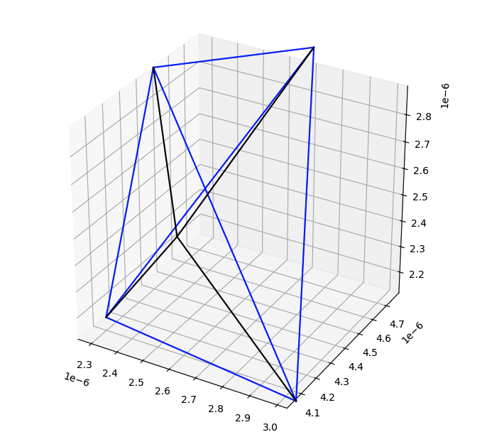
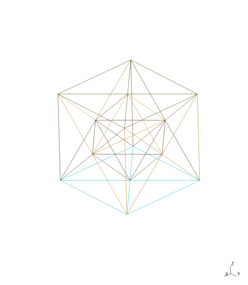
during one of my simulations I noticed some strange current values which seemed higher than expected, so I build the following MVP to test a really simple structure, which is based on the gmsh_diode3d example.

This example is a simple n-Volume where I set the doping und mobility in such a way, that the whole volume has a theoretical resistance of exactly 1 ohm. Addtionally, I used the extended precision and quite strict convergence criteria. I use devsim 2.6.4 and python 3.10.

# Copyright 2013 DEVSIM LLC
#
# SPDX-License-Identifier: Apache-2.0

from devsim import *
from devsim.python_packages.simple_physics import *
import diode_common

def print_currents(device, contact):
    """
    Print out contact currents
    """
    ece_name = "ElectronContinuityEquation"
    hce_name = "HoleContinuityEquation"
    contact_bias_name = GetContactBiasName(contact)
    electron_current= get_contact_current(device=device, contact=contact, equation=ece_name)
    hole_current    = get_contact_current(device=device, contact=contact, equation=hce_name)
    total_current   = electron_current + hole_current
    voltage = get_parameter(device=device, name=GetContactBiasName(contact))
    data = (voltage, electron_current, hole_current, total_current)
    print(f"{contact:10}{voltage:+.3e}\t{electron_current:+.3e}\t{hole_current:+.3e}\t{total_current:+.3e}")
    return data

def print_all_currents():
    """
    Prints all currents to console and returns outmap of values. !Currently only functional when all contacts are
    silicon contacts!
    :return:
    """
    print("\nSolution:")
    print("{0:10}{1:15}{2:12}{3:12}{4:10}".format("Contact", "Voltage", "Electron", "Hole", "Total"))
    print("                         Current     Current     Current")
    device_list = get_device_list()
    for device in device_list:
        contact_list = get_contact_list(device=device)
        outmap = {}
        for contact in contact_list:
                outmap[contact] = print_currents(device, contact)
    return outmap

device="diode3d"
region="Bulk"

diode_common.Create3DGmshMesh(device, region)
#diode_common.Create2DGmshMesh(device, region)

diode_common.SetParameters(device=device, region=region)
set_parameter(device=device, region=region, name="mu_n", value=1e5)
set_parameter(device=device, region=region, name="mu_p", value=1)

# this is the devsim format
write_devices (file="gmsh_diode3d_out.msh")

set_parameter(name="extended_solver", value="True")
set_parameter(name="extended_model", value="True")
set_parameter(name="extended_equation", value="True")

####
#### NetDoping
####
node_model(device=device, region=region, name="Acceptors", equation="0.0")
node_model(device=device, region=region, name="Donors",    equation="1.0/1.6*1e19")
node_model(device=device, region=region, name="NetDoping", equation="Donors-Acceptors;")

diode_common.InitialSolution(device, region)

####
#### Initial DC solution
####
solve(type="dc", absolute_error=1.0, relative_error=1e-12, maximum_iterations=100)

###
### Drift diffusion simulation at equilibrium
###

diode_common.DriftDiffusionInitialSolution(device, region)

solve(type="dc", absolute_error=1e-10, relative_error=1e-12, maximum_iterations=50)

v = 0.1
while v < 1.01:
    set_parameter(device=device, name=GetContactBiasName("top"), value=v)
    solve(type="dc", absolute_error=1e-10, relative_error=1e-12, maximum_iterations=30)
    print_all_currents()
    v += 0.1

element_from_edge_model(edge_model="ElectricField",   device=device, region=region)
element_from_edge_model(edge_model="ElectronCurrent", device=device, region=region)
element_from_edge_model(edge_model="HoleCurrent",     device=device, region=region)

write_devices(file="gmsh_nVolume_dd.dat", type="tecplot")
write_devices(file="gmsh_nVolume_dd.msh", type="devsim")
write_devices(file="gmsh_nVolume_dd.msh", type="vtk")

The simulation for the 3D case produces this result:

Solution:
Contact   Voltage        Electron    Hole        Total     
                         Current     Current     Current
bot       +0.000e+00	-2.866e+00	-7.336e-23	-2.866e+00
top       +1.000e+00	+2.866e+00	+7.336e-23	+2.866e+00

So instead of the expected current of 1 V / 1 ohm = 1A, I get around 2.9 A.

Performing the same simulation for the 2D case with “Create2DGmshMesh”:

Solution:
Contact   Voltage        Electron    Hole        Total     
                         Current     Current     Current
bot       +0.000e+00	-1.003e+05	-2.569e-18	-1.003e+05
top       +1.000e+00	+1.003e+05	+2.569e-18	+1.003e+05

Here the result looks a lot better with 1.003e5 A/cm * 1e-05 cm = 1.003 A, albeit not exact.

HI @GLuek

Unfortunately the 3d mesh example contains a bad mesh. For devsim to be accurate, it needs the mesh to be Delaunay, which is something that Gmsh does not guarantee. This is an experience I discuss in this paper I wrote:
https://doi.org/10.36227/techrxiv.14129081.v3

If you’d like, I can provide a Tetgen based example. Which yields better results Please let me know if you are interested?

In the end, I would like to have some kind of toolchain (open-source) to generate 3d models with a suitable mesh for devsim. Are the Gmsh 3D meshes bad in general? So even if I generate a new mesh like this with both algorithms set to delaunay:

import gmsh

gmsh.initialize()
gmsh.model.add("nVolume")
gmsh.option.setNumber("Mesh.MeshSizeFactor", 0.5)

# build bulk
id_bulk1 = gmsh.model.occ.addBox(0.0, 0.0, 0.0, 1.0, 1.0, 1.0, 1)

gmsh.model.occ.synchronize()

id_surf_top = gmsh.model.getEntitiesInBoundingBox(-0.1, -0.1, 0.9, 1.1, 1.1, 1.1, 2)[0][1]
id_surf_bot = gmsh.model.getEntitiesInBoundingBox(-0.1, -0.1, -0.1, 1.1, 1.1, 0.1, 2)[0][1]

# Physical Groups
grp_epi = gmsh.model.addPhysicalGroup(3, [id_bulk1], 1, "Bulk")

contact_diodeA = gmsh.model.addPhysicalGroup(2, [id_surf_top], 2, "top")
contact_diodeB = gmsh.model.addPhysicalGroup(2, [id_surf_bot], 3, "bot")

gmsh.model.occ.synchronize()

gmsh.option.setNumber("Mesh.MshFileVersion", 2.2)
gmsh.option.setNumber("Mesh.ScalingFactor", 1.0e-5)

"""
Mesh.Algorithm
    2D mesh algorithm (1: MeshAdapt, 2: Automatic, 3: Initial mesh only, 5: Delaunay, 6: Frontal-Delaunay, 7: BAMG, 8: Frontal-Delaunay for Quads, 9: Packing of Parallelograms, 11: Quasi-structured Quad)
    Default value: 6
    Saved in: General.OptionsFileName
    
Mesh.Algorithm3D
    3D mesh algorithm (1: Delaunay, 3: Initial mesh only, 4: Frontal, 7: MMG3D, 9: R-tree, 10: HXT)
    Default value: 1
    Saved in: General.OptionsFileName
"""
gmsh.option.setNumber("Mesh.Algorithm", 5)
gmsh.option.setNumber("Mesh.Algorithm3D", 1)

gmsh.model.mesh.generate(3)
gmsh.write("./gmsh_nVolume.msh")

Is it more viable to generate a structure in Gmsh and pipe it through tetgen for mesh generation? Ideally, I like to stick to gmsh at least for structure generation, but if you have a suggestion for a different 3D toolchain I will happily look into it.

Hi @GLuek

Thanks for your question Here is an email I had gotten concerning Delaunay mesh generation in Gmsh:
https://onelab.info/pipermail/gmsh/2020/013817.html

Hi Juan,

This is expected: to get a 3D mesh that satisfies the Delaunay criterion we would need to modify the surface mesh - this is something we try hard to avoid.

Christophe


> On 14 Jun 2020, at 20:17, Juan Sanchez <juan.e.sanchez at gmail.com> wrote:
> 
> Hello,
> 
> I am having a hard time getting a 3d delaunay mesh, so that the circumcenters of the tetrahedra are inside the element.
> 
> In my simulator, I am seeing that about 50% of the elements are not delaunay if:
> Mesh.CharacteristicLengthExtendFromBoundary = 1;
> 
> and about 90% are not Delaunay if:
> Mesh.CharacteristicLengthExtendFromBoundary = 0;
> 
> Is there a way to improve this when running the tool from the command line or with an option in the geo file?
> 
> I am using:
> /Applications/Gmsh.app/Contents/MacOS/gmsh -format msh2 -3  3dblock.geo
> 
> with version 4.5.6 on macOS 10.14.6 (Mojave).
> 
> Regards,
> 
> Juan

Please note that they are not guaranteeing the mesh to be Delauanay, because they do not want to change the surface mesh. Also note that there are a few algorithms, and the one specifically named “Delaunay” may not actually be the best one for generating a tetrahedral mesh.

Also note that while I’ve had some success with Tetgen:

  • I don’t know how to create the input for it from Gmsh
  • It may not always be able to find a good mesh.
  • I’ve only done a simple structure

A simulator like Synopsys Sentaurus and Silvaco both have workarounds that they use when they encounter non-Delaunay meshes, but these have not been implemented in devsim. I also don’t know how well they work in 3d.

One alternative toolchain is to use Coreform Cubit, which is a commercial version of a tool created by the US government:
https://coreform.com/

and I do have scripts to convert the mesh. The free version of Cubit is limited to 50,000 elements.

If you are able to generate input for Tetgen from Gmsh, that is great, and I’d appreciate your guidance on doing this.

I am not a meshing expert, but I am thinking if Gmsh is providing surface meshes to the underlying mesh tools, and that may create problems if points need to be added to fix bad meshes.

An excellent open source tool for 3D modelling is FreeCAD. But I don’t know if they have any 3D meshing plugins available yet.

Thanks for the feedback! I will try to make something work starting with tetgen and gmsh, if I accomplish anything I will let you know.

sounds good. please let me know if you need any help converting the meshes as I have a few scripts lying around.

Hello @GLuek

I have adopted an old script here:
https://github.com/devsim/devsim_misc/tree/main/misc

which shows bad tetrahedra in the block mesh. Running as default

python check_tetrahedra.py

shows the worst mesh element. Where the black lines go from each node of the tetrahedra to the circumcenter.

Unfortunately this center is outside of the tetrahedra, and is what leads to high current levels.

If uncomment line 69 of the script to show the first tetrahedra, instead of the worst, you see an example of where the circumcenter is inside of the element:

It also prints out the actual volume of the cube versus the volume if bad tetrahedra are present:

2.9185709233348095e-15	Volume calculated from tetrahedra edge volumes
9.999999999999989e-16	Volume from tetrahedra

Perhaps this could be tailored in your quest for a good mesh.

Thanks for the conversion and tetrahedra evaluation script @Juan. I tinkered a little with gmsh generation, tetgen meshing and the tetrahedra evaluation. Since it is a bit more code I put up an example project on github:

The tool flow in generell is: gmsh .stl → tetgen → convert to .msh → attach contacts via gmsh → check tetrahedra or devsim. Here is an image of a really simple mesh I generated with only 24 tetrahedra:

I am now at a point where I am a little lost how to proceed. The following image shows one tetrahedron of a mesh from the project which has a good quality:
good_tetrahedron
In the next step I scale the model by a factor of 10 without changing anything else, so the mesh basically stays the same, only the distance between the points changes:
bad_tetrahedron
The tetrahedra looks exactly as the one above as expected, but now the check_tetrahedra script shows a ratio between the devsim volume and tetrahedron volume of about 20.
When you plot the worst tetrahedra it looks like this:
worst_tetrahedron
As far as I understood this tetrahedron should not be too bad since the black lines do not extend beyond the blue volume.

Any ideas where to look next?

Hi @GLuek

I’m not sure. Potentially there could be a bug in the check_tetrahedra.py or somewhere else. Visually, the 2 figures look like they are scaled by a factor of 10. If the black lines meet somewhere inside or on the surface of the tetrahedron, then the ratio should be calculated as 1. This is since the 6 element edges should have there element node volumes sum up to the volume calculated from the 4 nodes

Are the Gmsh algorithms deterministic, and always write out the elements in the same order?

It is possible that meshing algorithms have problems with numerical precision, if you use mesh lengths that are too big or too small. For example, this one is Windows specific:
https://onelab.info/pipermail/gmsh/2007/002408.html

I would recommend reading and writing files with full precision, which it appears that you are already doing.

Use mesh lengths that don’t cause issues. For example, if the meshing algorithm has some hard coded bias against numbers like 1e-10, or 1e-15, then consider using lengths on the order of 1 or .1 and then scaling at the end.

Are the STL, gmsh, and Tetgen files each written out in full precision? Looking at your repo, they seem ok to me.

That is a really cool idea using STL, which I have never attempted before. Can you add the contacts before sending them to Tetgen?

Are you able to change the characteristic lengths in Tetgen so that the more tetrahedra are being used?

I can send you a tetgen input file that can create a good 3d block. However, it may depend on sizes you choose.

I am about ready to share with you an old tetgen example I used in a publication. I hope to have it up in a few hours, but it appears that my calculation of actual tetrahedral volume is giving weird results on macOS, but not Linux. I need to check if this is occuring on windows as well.

Hi @GLuek

It looks like there is a bug somewhere in devsim for the macOS and Windows platform. It is not occurring on Linux.

If you check out:
https://github.com/devsim/devsim_misc/tree/main/tetgenmesh
and run

python check_tetrahedra.py

it will say 100% of the tetrahedra are bad on Windows and macOS, but they are 0% on Linux.

I checked this on my site with the same results. With WSL2 the check_tetrahedron gives good results for my simple mesh above and the electrical simulation gives the expected result of 1A as well.

As far as I know the STL format has no support for defining entities beyond the surface mesh, so I think contacts and region have to be defined either in tetgen or afterwards in gmsh. But gmsh is quite helpful as it can “autodetect” the entities and define physical groups, but I have to take a deeper look if it changes the mesh even if I do not execute gmsh.model.msh.generate.

Thanks for the explanation. In gmsh, I am used to having many surfaces creating a closed surface for each region. Some of these surface are then also able to be treated as contact.

I have created a new release version 2.6.5. Please update and check to see if this resolves some of your meshing issue.

I updated the package and results on my windows installation look good now aswell. Thanks for your support! I will put some more work in the meshing toolchain and try to mesh more complex models, thanks again for the examples and scripts, they are really helpful.

1 Like

Thanks again for finding that bug on Windows and macOS.

If you run the final.sh script in the devsim_misc/tetgenmesh directory, it starts with a mesh with bad elements and it creates a background mesh .mtr file to make all of the elements Delaunay. The check_tetrahedra.py script in the directory has a commented out function to plot the circumsphere of the 4 nodes of the element of the worst elements.

Also, the ‘test.poly’ file marks the boundaries so that they can be used for contacts.

Hi @GLuek , this seems like amazing work!

I’m also interested in automatically generating simulations, but starting from a GDS layout + descriptions of the layers. We can already generate relatively complex CADs that I then mesh using GMSH constructive geometry. See a relatively simple 2D example here: Troubleshooting a faulty mesh? (we have done much crazier stuff for our FEM solvers)

How mature is your toolchain? I’m wondering it I can apply it, because my geometry parser can already generate 3D models. If I initially have physicals tagged (3D volumes and 2D interfaces/contacts), can we apply your fix to the mesh, and easily retag the physicals?

Hi @simbilod,

sorry for the late reply, I hadnt got access to my computer for a while.

I experimented with the toolchain from the github repo above: gmsh → stl → tetgen → gmsh → devsim but for more complex meshes I achieved roughly the same mesh quality as simply using gmsh <> devsim. I think I read somewhere, that the gmsh delaunay algorithms are adapted from tetgen anyway.

Nevertheless, attaching contacts to a mesh later via gmsh works, but due to the stl step in between all “descriptive” information is lost. Therefore you need to filter the vertices for e.g. a contact afterwards via EntitiesInBoundingBox or similar approaches.

I now use gmsh with the following algorithms:

gmsh.option.setNumber("Mesh.Algorithm", 5)
gmsh.option.setNumber("Mesh.Algorithm3D", 1)
gmsh.option.setNumber("Mesh.OptimizeNetgen", 1)
gmsh.option.setNumber("Mesh.MeshSizeExtendFromBoundary", 2)

My tooling looks roughly the same as yours. I read GDS layer data which is converted to 3D geometry and meshed by gmsh. The initial mesh is fed into devsim where GDS data is read and combined with z-doping profiles to generate the overall doping structure. Afterwards, I rewrote one of @Juan mesh refinement scripts to use the doping profile for background mesh generation which is fed back to gmsh for optimization.

In my opinion, a challenge in this approach is the generated mesh size. The isotropic mesh usually leads to a huge amount of vertices for semiconductor devices, since you have very thin layers with comparitively large xy dimensions. I searched for an axis-aligned anisotropic mesher similar to the SDE module from Sentaurus TCAD, but unfortunately I havent found anything.

2 Likes

Hi @GLuek

Have you seen LaGrit?

https://lagrit.lanl.gov/

This paper from 1997 makes it look appealing:
Unstructured 3D Grid Toolbox for Modeling and Simulation

and this semiconductor example:
https://lanl.github.io/LaGriT/pages/semiexamples.html

However my limited attempts to work with it were unsuccessful. It looks complicated to work with.

It produces Exodus files, which I would be able to provide scripts for. I have an exodus reader here:
https://github.com/devsim/devsim_3dmos/blob/main/ieee/meshing/cubit_test.py
and could tweak it as necessary if there are significant differences between Cubit and LaGrit

1 Like

Alternatively, do any of you have experience with GMSH aniso meshes?

There’s a 2D example: Gmsh 4.12.2

And they say there is experimental support in 3D for “MMG3D allows to generate anisotropic tetrahedralizations.”, used with a background mesh.

That does look interesting. One of the requirements for devsim is an Delaunay mesh. I don’t know enough about the method to see if this is achieved. If you see a bunch of obtuse 2D triangles, that is a good sign that the Delaunay criterion is not met.

In 3D, the other Gmsh algorithms are “Constrained Delaunay”, which are only “mostly” Delaunay.

An octree mesher is interesting, as there are only right angle Triangles and Tetrahedra. Also a prism mesh is also good, where you are pulling the triangles into the 3rd dimension, but it has a lot of limitations in the type of structures you can build.