What I don’t understand is how can the electron current (hole current) be so high in the P region (N region)? Aren’t all electrons supposed to eventually recombine one they cross the depletion zone?
In most textbooks I studied, the current densites of minority carriers in the regions tend to 0 as we depart from the depletion zone. Am I missing something here?
Thank you for your help with this very basic question,
If the diode is short, then there is not enough distance for all of the minority carriers to recombine. In this particular example, most of the recombination is occurring in the space charge region.
So the recombination is then happening in the contact. TCAD simulators report the electron and hole current at the contact. In an actual device with real contacts, there would only be the electrons coming out of the contact.
You can try the TCAD app and experiment with the parameters for the 1D diode example.
Thank you so much for your response. I took some time to think about what you told me.
However, I’m still trying to figure it out.
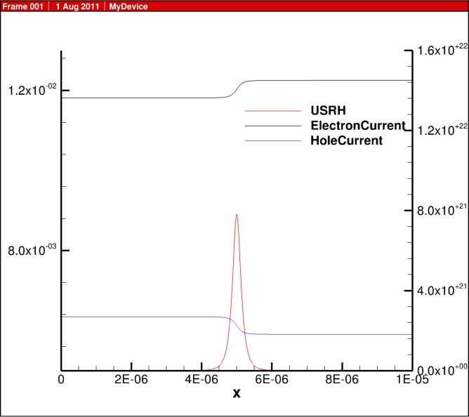
In the example I posted, the diode isn’t “short/small” right? So most of the recombination is happening in the depletion zone, and the contacts are “far” from that zone. Then I don’t understand for example why electron current is so high at x=2e-6.
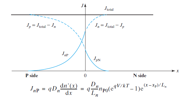
How can I relate to the following situation I find in textbooks?
The minority current is unlikely to go to zero in each region. The currents you see may change orders of magnitude, by changing the parameters.
The recombination relies on these parameters:
taun
taup
n1
The currents also depend on the length of the depletion region. That depends on the doping in each region:
Donors
Acceptors
For a “short” diode, the current also depends on the distance of the edge of the depletion region to the contact.
The contacts are ohmic, meaning that the holes and electrons at each contact are also determined by the doping.
If you reduce the recombination lifetimes, taun and taup, that should reduce the minority currents at the contact. If you reduce the Donor doping, that should reduce the number of electrons at the edge of the depletion region on the p side. I think this would be n_{P0} in your figure.
The figure you attached is at an arbitrary scale and length. It may be zoomed in to near the depletion region, and not showing the contacts.
Also, the higher the forward bias, the more current is going to be induced. Since current is exponential with bias, you can start seeing high electron currents in the p region.