dear all,
i am trying to simulate pin diode behavior under reverse bias. The goal is to simulate the plasma movement during reverse recovery. Is it possible to do so with DEVSIM?
my best,
Saidon70
It should be possible. It may require some work to script the models needed. For example, to add the Avalanche model please see Impact ionization example
Dear Juan,
thank you for your replay and I appreciate your time.
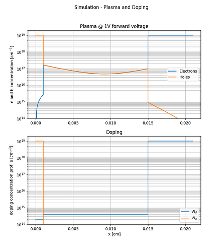
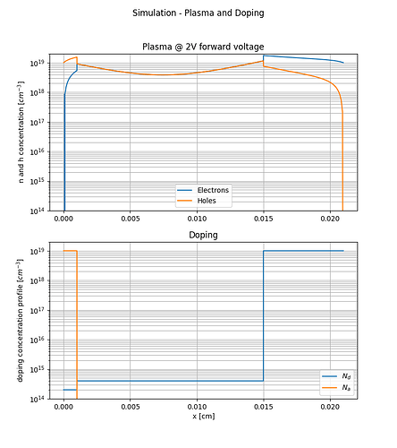
I build a Si pin diode model which works very well when the diode is forward biased as can be seen from the attached figures.
However, when the diode is reversed biased I get the following error at -10V:
error: DEVSIM FATAL: while evaluating node model IntrinsicHoles:Potential on Device: Si_PiN on Region: Region
There was a Overflow floating point exception while evaluating pow(IntrinsicElectrons,(-2))
while evaluating model IntrinsicHoles:Potential: expression (-pow(IntrinsicElectrons,(-2)) * pow(n_i,2) * IntrinsicElectrons:Potential) evaluates to invalid
I did not implement the impact ionization following the example you kindly sent and I don’t think that this error is related to impact ionization because the reverse bias voltage is relativity low (-10V). The introduced pin diode model is supposed to block more that 1200V. I am trying to plot the electric field and potential in the n- drift layer. By the why, the error happens only when trying to use write_devices(file="pin_si_diode_rb", type="vtk"). I am not sure if this information is helpful.
For completeness I am attaching the simulation script. I hope you can advice on what I am missing here.
My best,
Said
#!/usr/bin/env python3
# -*- coding: utf-8 -*-
"""
Created on Wed Sep 18 21:41:49 2024

@author: seb
"""

from devsim import *
from devsim.python_packages.simple_physics import *
from devsim.python_packages.ramp import *
from devsim.python_packages.model_create import CreateSolution

import numpy as np
import matplotlib.pyplot as plt

reset_devsim()

contactcharge_edge = "contactcharge_edge"
ece_name = "ElectronContinuityEquation"
hce_name = "HoleContinuityEquation"
# celec_model = "(0.5*abs(NetDoping+(NetDoping^2 + 4 * n_i^2)^(0.5)))"
# chole_model = "(0.5*abs(-NetDoping+(NetDoping^2 + 4 * n_i^2)^(0.5)))"
celec_model = "(1e-9 + 0.5*abs(NetDoping+(NetDoping^2 + 4 * n_i^2)^(0.5)))"
chole_model = "(1e-9 + 0.5*abs(-NetDoping+(NetDoping^2 + 4 * n_i^2)^(0.5)))"

q       = 1.6e-19  # coul
k       = 1.3806503e-23  # J/K
eps_0   = 8.85e-14  # F/cm^2
eps_si  = 11.1
eps_ox  = 3.9
n_i     = 1.0e10  # #/cm^3

mu_n    = 400 #1350 #400
mu_p    = 200 #480  #200
tau_n   = 2e-6
tau_p   = tau_n/3


# Doping
Na_body = 1e+19
Nd_drift= 2e+14
Nd_subs = 1e+19
W_d     = 140e-6

name="Si_PiN_Diode"


#All values in cm
def Create2DMesh(device, region):
    create_2d_mesh(mesh="dio")
    add_2d_mesh_line(mesh="dio", dir="x", pos=0,      ps=1e-4) # P_bode
    add_2d_mesh_line(mesh="dio", dir="x", pos=10e-4,  ps=0.8e-6) # P body
    add_2d_mesh_line(mesh="dio", dir="x", pos=80e-4,  ps=1e-4) # N_minus
    add_2d_mesh_line(mesh="dio", dir="x", pos=150e-4, ps=0.8e-6) # N_minus
    add_2d_mesh_line(mesh="dio", dir="x", pos=210e-4, ps=1e-4) # N_plus

    add_2d_mesh_line(mesh="dio", dir="y", pos=0,      ps=0.5e-4) # y
    add_2d_mesh_line(mesh="dio", dir="y", pos=30e-4,  ps=0.5e-4) # y

    add_2d_mesh_line(mesh="dio", dir="x", pos=-1e-4,  ps=1e-4)  # top metal
    add_2d_mesh_line(mesh="dio", dir="x", pos= 211e-4,ps=1e-4)  # bot metal

    add_2d_region(mesh="dio", material="Si", region=region)
    add_2d_region(mesh="dio", material="SiC", region="air1", xl=-1e-4,  xh=0)
    add_2d_region(mesh="dio", material="SiC", region="air2", xl=210e-4, xh=211e-4)

    add_2d_contact(mesh="dio", name="top", material="metal", region=region, yl=0, yh=30e-4, xl=-1e-4, xh=0, bloat=1e-10)
    add_2d_contact(mesh="dio", name="bot", material="metal", region=region, xl=210e-4,   xh=211e-4, bloat=1e-10)

    finalize_mesh(mesh="dio")
    create_device(mesh="dio", device=device)
    write_devices(file="si_pin_diode_mesh", type="vtk")

def SetNetDoping(device, region):
    '''
      NetDoping
    '''
    CreateNodeModel(device, region, "Acceptors", str(Na_body)+"*step(10e-4-x)") # P doping
    CreateNodeModel(device, region, "Donors",    str(Nd_drift) + "*(step(-10e-4+x)+step(150e-4-x))" + "+" + str(Nd_subs) + "*step(-150e-4+x)") # N- doping
    CreateNodeModel(device, region, "NetDoping", "Donors-Acceptors")


def InitialSolution(device, region, circuit_contacts=None):
    # Create Potential, Potential@n0, Potential@n1
    CreateSolution(device, region, "Potential")

    # Create potential only physical models
    CreateSiliconPotentialOnly(device, region)


    # Set up the contacts applying a bias
    for i in get_contact_list(device=device):
        if circuit_contacts and i in circuit_contacts:
            CreateSiliconPotentialOnlyContact(device, region, i, True)
        else:
            ###print "FIX THIS"
            ### it is more correct for the bias to be 0, and it looks like there is side effects
            set_parameter(device=device, name=GetContactBiasName(i), value=0.0)
            CreateSiliconPotentialOnlyContact(device, region, i)


def DriftDiffusionInitialSolution(device, region, circuit_contacts=None):
    ####
    #### drift diffusion solution variables
    ####
    CreateSolution(device, region, "Electrons")
    CreateSolution(device, region, "Holes")

    ####
    #### create initial guess from dc only solution
    ####
    set_node_values(device=device, region=region, name="Electrons", init_from="IntrinsicElectrons")
    set_node_values(device=device, region=region, name="Holes",     init_from="IntrinsicHoles")

    ###
    ### Set up equations
    ###
    CreateSiliconDriftDiffusion(device, region)
    for i in get_contact_list(device=device):
        if circuit_contacts and i in circuit_contacts:
            CreateSiliconDriftDiffusionAtContact(device, region, i, True)
        else:
            CreateSiliconDriftDiffusionAtContact(device, region, i)

def SetSiliconParameters_my(device, region, T):
    """
    Sets physical parameters assuming constants
    """
    #### TODO: make T a free parameter and T dependent parameters as models
    set_parameter(
        device=device, region=region, name="Permittivity", value=eps_si * eps_0
    )
    set_parameter(device=device, region=region, name="ElectronCharge", value=q)
    set_parameter(device=device, region=region, name="n_i", value=n_i)
    set_parameter(device=device, region=region, name="T", value=T)
    set_parameter(device=device, region=region, name="kT", value=k * T)
    set_parameter(device=device, region=region, name="V_t", value=k * T / q)
    set_parameter(device=device, region=region, name="mu_n", value=mu_n)
    set_parameter(device=device, region=region, name="mu_p", value=mu_p)
    # default SRH parameters
    set_parameter(device=device, region=region, name="n1", value=n_i)
    set_parameter(device=device, region=region, name="p1", value=n_i)
    set_parameter(device=device, region=region, name="taun", value=tau_n)   #0.2e-6
    set_parameter(device=device, region=region, name="taup", value=tau_p) #0.045e-6
    set_parameter(device=device, region=region, name="bot", value=0.0) #0.045e-6


if __name__=='__main__':
    dev='Si_PiN'
    region='Region'
    Create2DMesh(dev,region)
    SetSiliconParameters_my(dev, region, 300)
    # set_parameter(name = "extended_solver", value=True)
    # set_parameter(name = "extended_model", value=True)
    # set_parameter(name = "extended_equation", value=True)

    SetNetDoping(dev, region=region)

    InitialSolution(dev, region)
    solve(type="dc", absolute_error=1e5, relative_error=1e-12, maximum_iterations=50)
    write_devices(file="si_diode_e", type="vtk")


    DriftDiffusionInitialSolution(dev, region)
    solve(type="dc", absolute_error=1e5, relative_error=1e-12, maximum_iterations=100)

    FWB=False # False for reverse bias

    fw_voltage=1
    bw_voltage=-10
    if FWB==True:
        rampbias(dev, "top",fw_voltage,0.2,0.001, 60, 1e-12, 1e5, printAllCurrents)
        write_devices(file="pin_si_diode_fw", type="vtk")

    else:
        rampbias(dev, "top",bw_voltage,2,0.01, 60, 1e-12, 1e5, printAllCurrents)
        # delete_node_model(device=dev, region=region, name="IntrinsicElectrons")
        # delete_node_model(device=dev, region=region, name="IntrinsicHoles")
        # for i in np.linspace(0, 10, 20):
        #     print(f'###############    {-i:2.2f}     ################')
        #     set_parameter(device=dev, name=GetContactBiasName("top"), value=-i)
        #     solve(type="dc", absolute_error=1e5, relative_error=1e-9, maximum_iterations=100)
        print('###############    finished     ################')

        write_devices(file="pin_si_diode_rb", type="vtk")


    #%%
    fig,ax=plt.subplots(2,1,figsize=(8,9))
    x=get_node_model_values(device=dev, region=region, name="x")

    if FWB==True:
        fig.suptitle('Simulation - Plasma and Doping')
        y_e=get_node_model_values(device=dev, region=region, name="Electrons")
        y_h=get_node_model_values(device=dev, region=region, name="Holes")
        y_d=get_node_model_values(device=dev, region=region, name="Donors")
        y_a=get_node_model_values(device=dev, region=region, name="Acceptors")

        ax[0].set_title(f'Plasma @ {fw_voltage}V forward voltage')
        ax[0].semilogy(x,y_e,label='Electrons')
        ax[0].semilogy(x,y_h,label='Holes')
        ax[0].set_ylim([1e14,2e19])
        ax[0].set(ylabel='n and h concentration [$cm^{-3}$]')
        ax[0].legend()
        ax[0].grid(which='both')

        ax[1].set_title('Doping')
        ax[1].semilogy(x,y_d,label='$N_d$')
        ax[1].semilogy(x,y_a,label='$N_a$')
        ax[1].set_ylim([1e14,2e19])
        ax[1].set(ylabel='doping concentration profile [$cm^{-3}$]')
        ax[1].set(xlabel='x [cm]')
        ax[1].legend()
        ax[1].grid(which='both')
        fig.savefig(f'{name}_at{fw_voltage}V.png')

    else:
        fig.suptitle('Simulation - Plasma and Doping')

        # y_E=get_node_model_values(device=dev, region=region, name="ElectricField")
        y_phi=get_node_model_values(device=dev, region=region, name="Potential")


        ax[0].set_title('Plasma')
        # ax[0].plot(x,y_E,label='E-Field')
        ax[0].plot(x,y_phi,label='Potentia.')
        # ax[0].set_ylim([1e14,2e19])
        ax[0].set(ylabel='n and h concentration [$cm^{-3}$]')
        ax[0].legend()
        ax[0].grid(which='both')

        # ax[1].set_title('Doping')
        # ax[1].semilogy(x,y_d,label='$N_d$')
        # ax[1].semilogy(x,y_a,label='$N_a$')
        # ax[1].set_ylim([1e14,2e19])
        # ax[1].set(ylabel='doping concentration profile [$cm^{-3}$]')
        # ax[1].set(xlabel='x [cm]')
        # ax[1].legend()
        # ax[1].grid(which='both')
It looks like a model used for the potential only solution is blowing up. Since it is not needed for visualization, you can apply a filter when writing the data.
Please try:
write_devices(file="pin_si_diode_rb", type="vtk",
    include_test=lambda x: not x.startswith('Intrinsic'))
so that any Intrinsic model is excluded from the data file. Please see this link for more information:
https://devsim.net/releasenotes.html#reduction-in-data-file-sizes
Dear Juan,
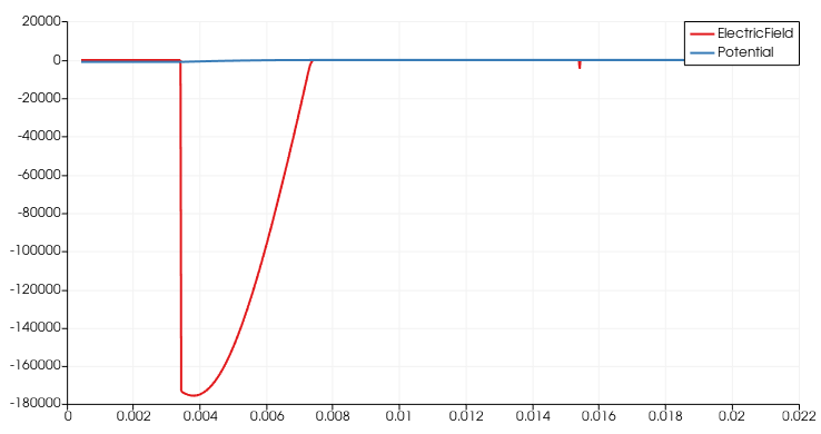
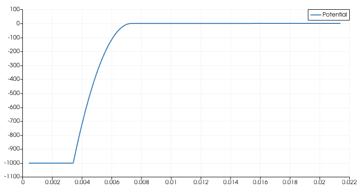
thanks for the hint. After changing to write_devices(file="pin_si_diode_rb", type="vtk", include_test=lambda x: x in ('ElectricField','Potential', )) I was able to complete the simulation successfully up to -1000V and even higher as can be seen in the following figures.
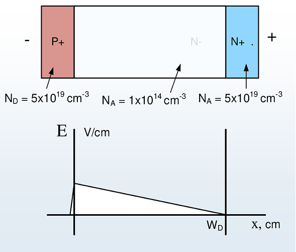
The electric field shape does not reflect the known triangular shape seen in text books in the case of none punch through (see figure below). Is there any explanation for this behavior?
My best,
Said
Thanks for the updating. I suggest checking whether the node spacing is refined enough for your simulation.
