Hello Juan, thank you for your continued updates for DEVSIM. Recently, I am interested in transient device simulation. I want to use DEVSIM to study the transient characteristic of field effect transistors like MOS. I am trying to learn the given examples like tran_diode.py, but I have some questions:
- what is the connection between the “voltage” , “acreal” and “acimag” for the voltage source?What is the expression for a voltage source?:
devsim.circuit_element(
    name="V1", n1=GetContactBiasName("top"), n2=0, value=voltage, acreal=1.0, acimag=0.0
)
- In
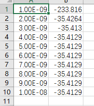
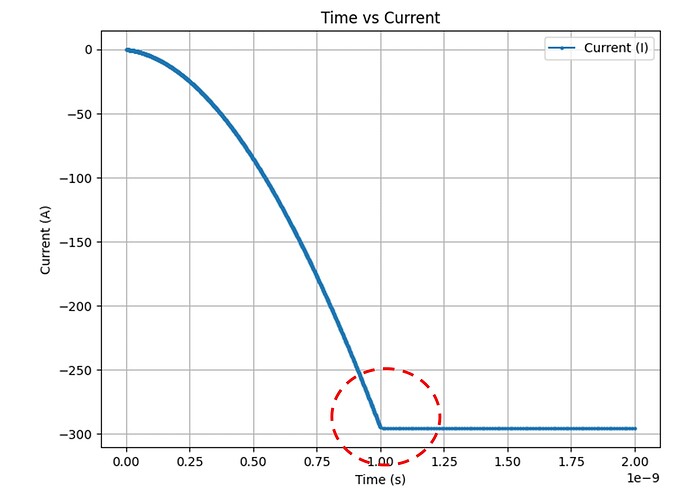
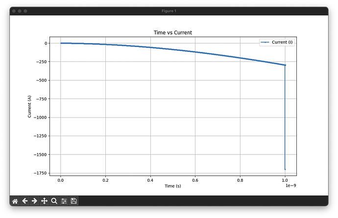
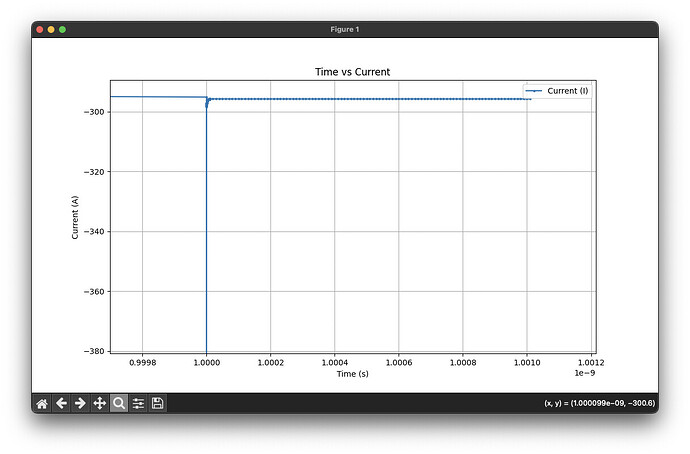
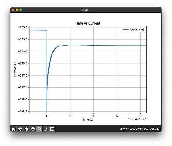
tran_diode.py, I set a small time step to capture the transient current changes following an applied voltage. However, with a very small time step, the initial output current becomes unusually large and appears dependent on the time step size. Additionally, I am not observing the expected transient change in the current. For example, whentime_step=1e-9, this issue is particularly noticeable.:
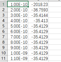
And smaller time_step=1e-10:
The code is below:
import devsim
from devsim.python_packages.simple_physics import GetContactBiasName
import diode_common
import csv


def print_circuit_solution():
    for node in devsim.get_circuit_node_list():
        r = devsim.get_circuit_node_value(solution="dcop", node=node)
        print("%s\t%1.15e" % (node, r))


device = "MyDevice"
region = "MyRegion"

# Set extended parameters
devsim.set_parameter(name="extended_solver", value=True)
devsim.set_parameter(name="extended_model", value=True)
devsim.set_parameter(name="extended_equation", value=True)

# This requires a circuit element to integrated current
voltage = 0.0
devsim.circuit_element(
    name="V1", n1=GetContactBiasName("top"), n2=0, value=voltage, acreal=1.0, acimag=0.0
)

diode_common.CreateMesh2(device=device, region=region)
diode_common.SetParameters(device=device, region=region)

# Übergeben der Werte an SetNetDoping
diode_common.SetNetDoping(device=device, region=region)

diode_common.InitialSolution(device, region, circuit_contacts="top")

# Initial DC solution
devsim.solve(type="dc", absolute_error=1.0, relative_error=1e-12, maximum_iterations=30)

diode_common.DriftDiffusionInitialSolution(device, region, circuit_contacts=["top"])

devsim.solve(
    type="transient_dc", absolute_error=1.0, relative_error=1e-14, maximum_iterations=30
)

print_circuit_solution()

devsim.circuit_alter(name="V1", value=0.7)

time_step = 1e-10
total_time = 1e-9
current_time = 0

while current_time < total_time:
    devsim.solve(
        type="transient_bdf1",
        absolute_error=1e10,
        relative_error=1e-10,
        maximum_iterations=30,
        tdelta=time_step,
        charge_error=1,
    )

    print_circuit_solution()
    current_time += time_step

    current_V1I = devsim.get_circuit_node_value(solution="dcop", node="V1.I")
    with open("current_vs_time.csv", mode='a', newline='') as file:
        writer = csv.writer(file)
        writer.writerow([current_time, current_V1I])

    print(current_time)
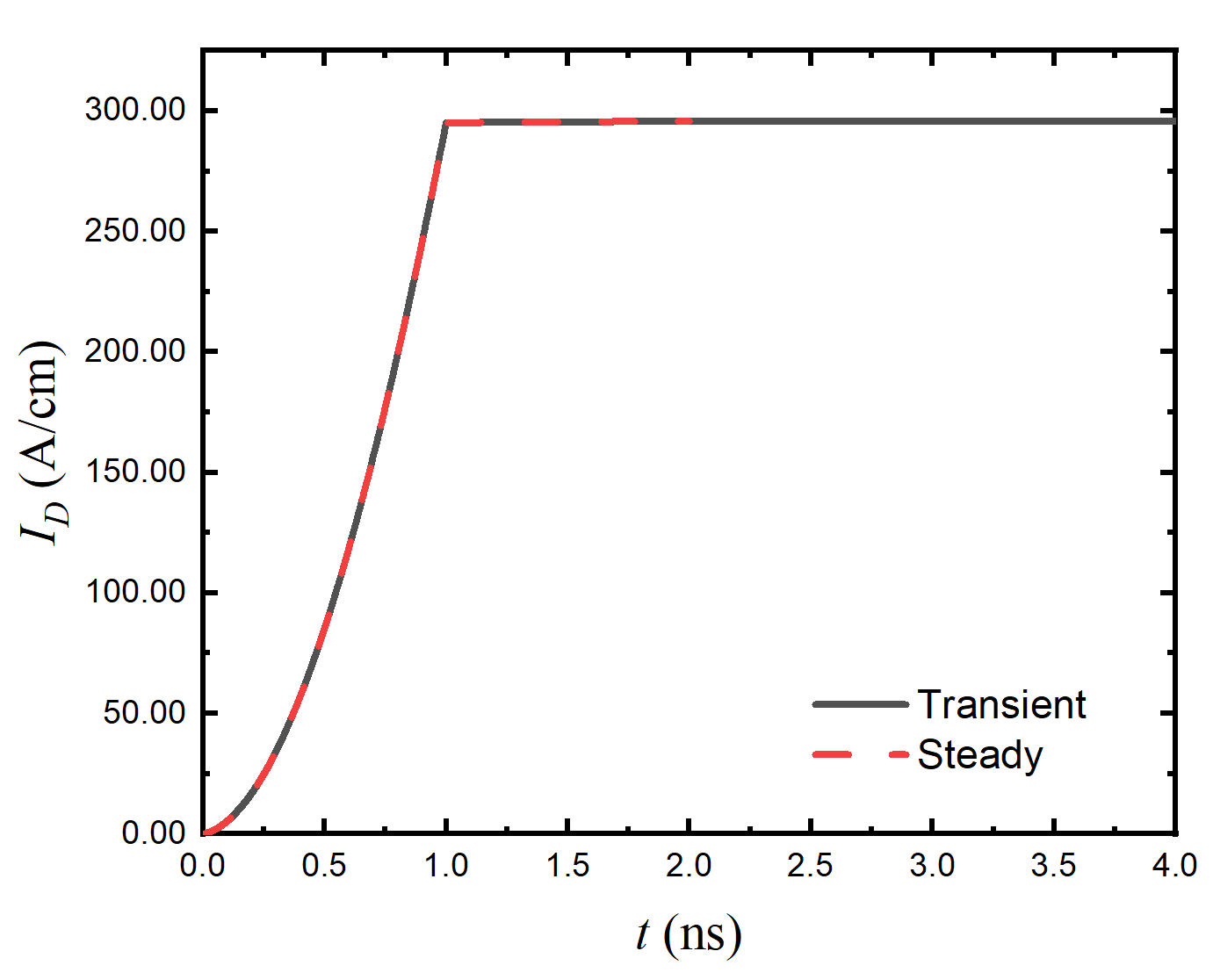
And I find that the current reaches stability quickly and seems more dependent on the number of iterations than on time itself. Why?
- I’m looking to apply a periodically changing signal, like a simple square wave, to the device to simulate high-frequency operation. Do you have any advice on how to set up this kind of signal in DEVSIM?
Thank you very much for any suggestions and guidance!
