Hi Juan!
Sorry to bother you.Before, the temperature boundary and voltage boundary I set during the electro-thermal simulation are at the same position, so I can set the temperature boundary without adding additional contacts. But now I want to add temperature boundaries where the voltage is not applied. But when I added additional contacts, I found that if no additional processing is performed on the contacts, the equations of the electrical part will also be affected. I wonder if there is a way to add boundary conditions that are unique to the heat conduction equation?
I recommend to make sure the contacts are not sharing any nodes, as this can cause conflict between the boundary conditions.
It is possible to only specify a Temperature equation for a contact, without specifying any other equations. If Temperature is the only variable in the equation, it can still affect the temperature used in your carrier and potential equation.
Hi Juan!
I don’t know if I misunderstand your advice. Below is the structure which I am calculating:
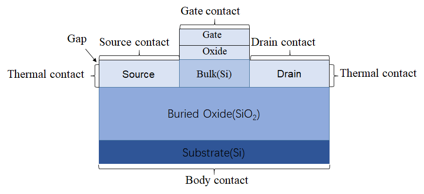
I add the note about the original contact and the the thermal contact I added. And I left a little gap to avoid different contact sharing nodes. In the calculation, I don’t set any equation or parameter in the thermal contact (include thermal boundary temperature, I set the bulk contact temperature in both example). What I do is just add them in the gmsh file and device. This is their ouput:
First is which didn’t add thermal contact:
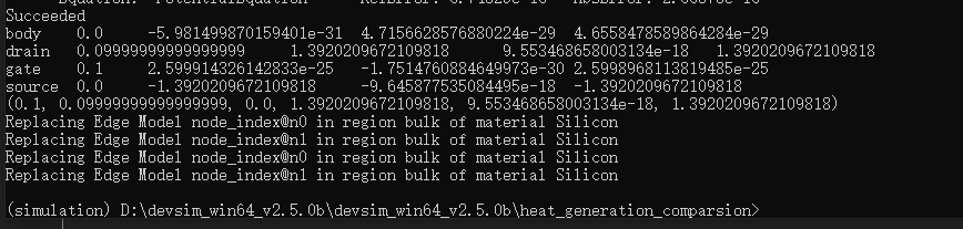
Second is which added thermal contact:
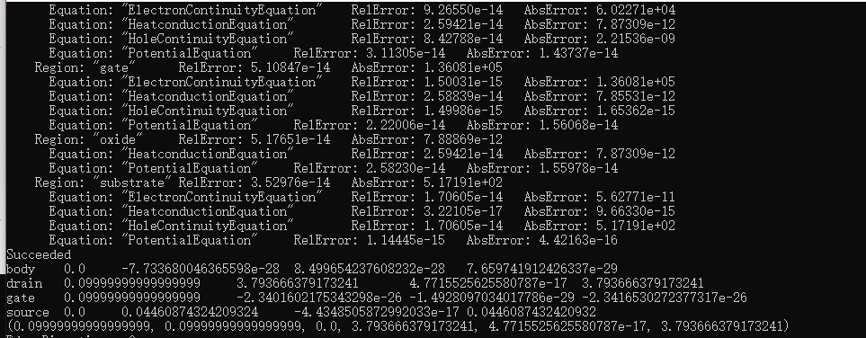
They are different obviously. Most important is that the absolute value of drain current and gate current is different after I add thermal contact. This is not right I think. So I wonder if there some default equation or setting in the contact. So after I add contact, it will influence the equations for the electrical part certainly.
Besides, there is another question I want to ask you. It is about the edge model. I found that the value of the most edge models will appears a fluctuation. For example, the potential and the electric field in the mobility example of Devsim:
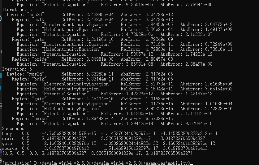
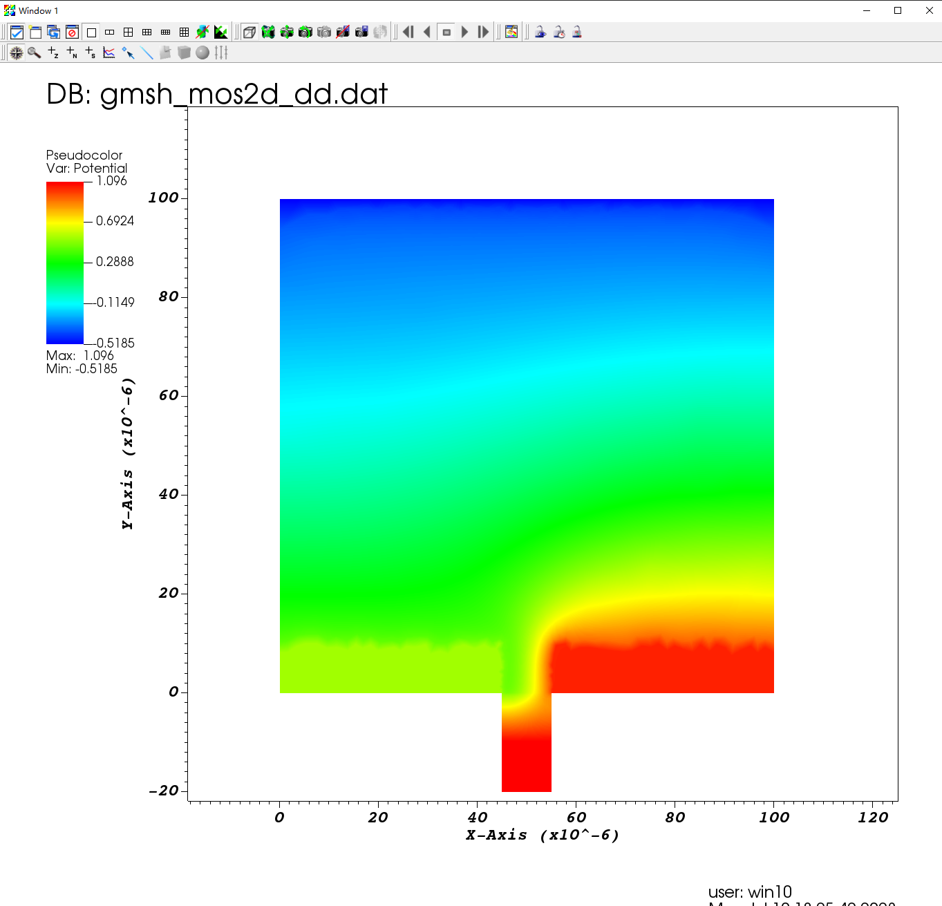
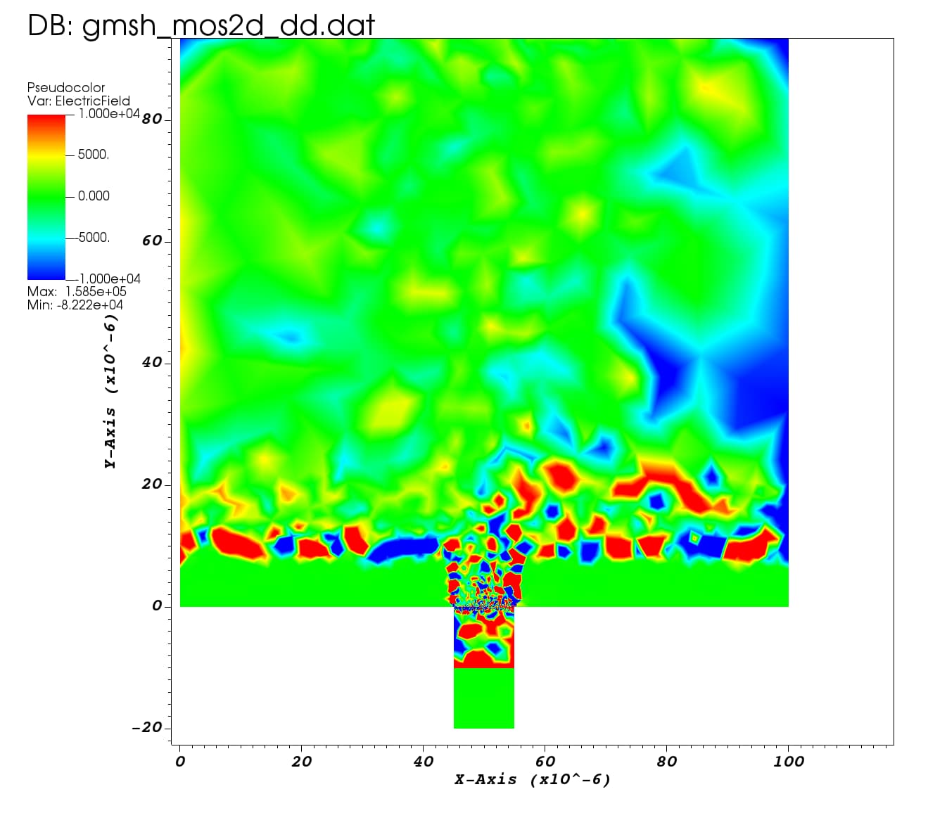
We can see that the potential is smooth but the electric field in the VISIT changes strangely. In my calculations, the values of the edge models also exhibit wild positive and negative fluctuations. Why this happened? And I have done some verification with the Silvaco (commercial TCAD). The I-V curve of my example is very closed to Silvaco which can prove the correctness of Devsim I think. But the fluctuations of the values of edge model confuse me a lot in the VISIT. Is this possible because the positive and negative recognition of the edge model in VISIT is different from that in Devsim?
The edge model for ElectricField does not work very well in visualization. It is best to convert the edge electric field using:
https://devsim.net/CommandReference.html#devsim.element_from_edge_model
to convert the edge electrical field to triangle electric field components:
element_from_edge_model(device=device, region=region, edge_model="ElectricField")
as ElectricField_x, ElectricField_y. These can then be visualized using a vector calculation in Visit.
If you are only interested in the magnitude, you can then do:
element_model(device=device, region=region, name="Emag", equation="(ElectricField_x^2 + ElectricField_y^2)^(0.5)")
For the gate currents, those should be close to 0, unless you have some type of gate tunneling implemented. The current into the gate is then numerical noise.
For the drain and the source currents, I would expect that the results would match if the thermal contacts are set to the same temperature as the original simulation. There are some details required to make sure that the temperatures are included properly in all of the models.
Also to be safe, please make sure that your thermal contacts on the source and drain do not touch the buried oxide. This is since the contact and interface boundary conditions can conflict.
Thank you very much, Juan. The “element_from_edge_model” is useful to visualize the edge model. But I try the thermal contact again, it still not works well. Although I set isothermal simulation, and use uniform temperature, the results which adds two new contacts are still different with the original simulation. I decide to use Silvaco to calculate this part. I’ll appreciate your suggestions!