Using gmsh_mos2d.py to make a 3D mos

Hello @Juan ,

I have been trying to use the example code form gmsh_mos2d.py to build a similar simulation for a 3D mos model and I’ve been having some trouble with it.

In order to check my results, I’ve been comparing the results from the 2D vs the 3D model and, so far, they do not match.
First of all, I used a slightly different mesh for the 2D model compared to gmsh_mos2d.msh. The .geo file looks like this:


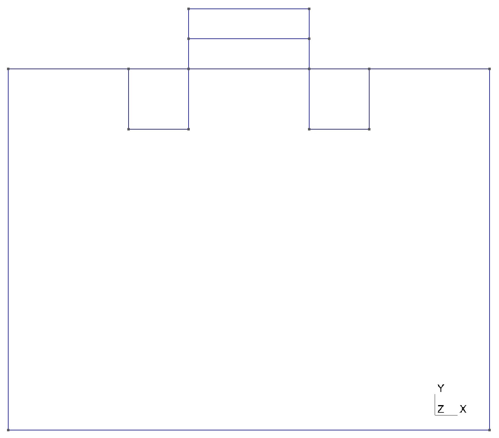
The 3D model follows the same idea, where a slice through the middle would match the 2D model.
With this setup there are more Physical Groups, so I’ve added the appropriate regions, interfaces(using test_convert.py), and contacts in gmsh_mos2d.py. I also changed some of the numbers in gmsh_mos2d_create.py to match the new dimensions of the model.
I tried starting with keeping all the materials as Silicon except for the Oxide under the gate, as in the original file, but simplified the doping a little bit. I also changed the biases to this:

rampbias(device, "gate",  -5.0, 0.5, 0.001, 20, 1e-1, 1e30, printAllCurrents)
rampbias(device, "drain", 1.0, 0.1, 0.001, 20, 1e-1, 1e30, printAllCurrents)
rampbias(device, "source", 0.5, 0.1, 0.001, 20, 1e-1, 1e30, printAllCurrents)

I compared the results using VisIt and also by looking at the results of calling PrintCurrents through
rampbias, which gave different results (Note: I saw in a previous discussion that there is an updated ramp.py file, so I used this one https://github.com/devsim/devsim/blob/main/python_packages/ramp.py):
2D:

bot 0.0 -1.1165946715078126e-18 -3.886271738199074e-22 -1.1169832986816324e-18
drain   0.9999999999999999   4.50067270015629e-30   2.343283271088381e-16  2.343283271088426e-16
gate    -0.5    0.0 0.0 0.0
source  0.5  -1.3474416471117283e-28  1.2170653698713034e-14  1.21706436987129e-14

3D:

bot 0.0 8.017909316301693e-24 -1.1649885648584984e-27 8.016744327736834e-24
drain   0.9999999999999999  1.3860821922210861e-34  -5.963212823507075e-20 -5.963212823507061e-20
gate    -5.0    0.0 0.0 0.0
source  0.5  -3.8033789185931215e-33  -7.953646185623621e-20  -7.953646185624002e-20

I’m not too confident that I understand how some of the variables in gmsh_mos2d_create.py are used, so I’m no sure what changes I would still need to make for the 3D model.
Do you know what I’m missing?

Also, when I display the results in VisIt, it tells me that it doesn’t have any information about the Electron and Hole Currents, despite having continuity equations at the interfaces (but the Potential works fine). The same happens when I try to display the Acceptors, Donors, Holes, and Electrons.
Do you know why this is happening?

Also, I’m not sure if this could somehow help with figuring this out, but in one your presentations named “Semiconductor Device Simulation Using DEVSIM” (2018), you had some results of the 2D MOSFET in slides 6 and 7. After running gmsh_mos2d.py and gmsh_mos2d_kla.py I realized that the results from running these files were not the same as the ones in the presentation. So I was curious, what were the changes in the code to get those results?

PS: I know I have a pretty large relative error right now, but I’m planning to spend more time figuring out the smallest possible error after getting everything else to work. I’m also using the same errors right now for both 2D and 3D.

Hi @katzir

As mentioned in a previous topic, the MOSFET examples are not really tuned, and mostly used for testing. Please see these post and see if they are helpful for getting a good 2D simulation.
I want to see Id- Vgs Curve
I want to modify gmsh_mos2d.py

Getting a good mesh in 3D is difficult. For our IEEE publication, we ended up using a proprietary meshing tool for the the 3D mesh result. Conceivably, it should be possible to get this working with Gmsh, using the refinement approach I reference in one of the linked topics above.

Please see the refinement code for 2d here:
https://github.com/devsim/devsim_misc/tree/main/refinement

There is code in the refinement scripts in 3D, but it may require some additional testing to make sure it works.

Please note that the simulation files we used in this publication:
https://doi.org/10.1109/TED.2021.3094776

have some fixes, including to using the appropriate driving force for velocity saturation. I think the high field mobility model may also have some changes.

I will release these files soon.

I have gone ahead and published the MOS simulation files used in the IEEE publication:
https://github.com/devsim/devsim_3dmos

This should enable further discussion about this topic.

There is a 3d mos geo file here:
testing/gmsh_mos3d.geo
in the devsim distribution. I recommend an approach using boolean approach, such as some of the 3d examples, including the unfinished finfet example here:
https://github.com/devsim/devsim_misc/tree/main/finfet_ex/finfet

Hello @Juan

Thank you for the files! I installed some packages that I was missing and I’ve trying to get the files in devsim_3dmos to work, but I haven’t been able to make much progress.
Based on how files are imported, I’m guessing either idvd.py or build.py is supposed to run first.
I tried both, but idvd.py gives me this error:


I think this means I need to give it some input for lines 37-42 to work, but I’m not sure what files to give it. Are there any files in this folder that I should use?
Then when I try to run build.py I get this error:

ModuleNotFoundError: No module named ‘cubit’

I looked for any packages named cubit I could install through pip and through the environments in Anaconda.Navigator but I couldn’t find anything. I also checked if there was a file with that name in a different directory but I didn’t find it, so I’m not sure how to run this file either.
Is there something I may have misunderstood or maybe I’m missing?

You will not be able to build a new structure, without using Cubit, a proprietary program from:
https://coreform.com/

The cubit module is their Python API. They do have a free student version, but it is limited in the number of elements.

You can still run the simulations from the mesh that I have provided. Please see this script, which was used to generate the simulation results in the published paper:
https://github.com/devsim/devsim_3dmos/blob/main/ieee/sweeps.sh

The physics files are still valid, if you wanted to create a 3D device using Gmsh.

If you want to use Cubit, the free student version can be used if you can keep your structure below 50,000 elements.
https://coreform.com/products/coreform-cubit/free-meshing-software/

Please note that DEVSIM is limited to using tetrahedral meshes in 3d and triangular meshes in 2d.

Thank you for the explanation! I’ll try it out and get back to you if I run into any issues.

1 Like