I am running again,I will report it to you immediatly

Thanks for sharing the screenshot. It doesn’t look like your cpu is being time limited using this method. You may want to clarify with your sysadmin if there are any other cpu limitations being enforced.
I will let you know if my current run completes. It will be running for a while.
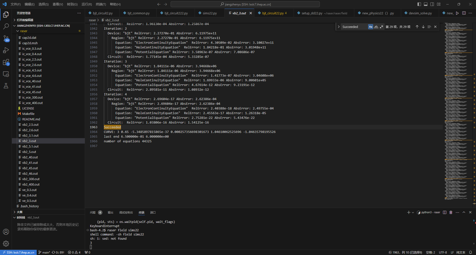

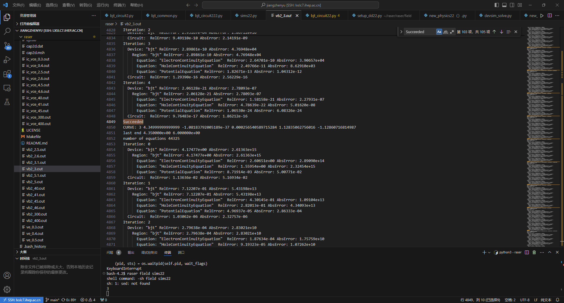
I think that It’s an initial success. ![]()
But I don’t understand why there are many “9” after the decimal point, is this normal and what is causing it?
I’m glad that it is working better for you now. The issue with the repeating decimal 9 is that 0.01 is not representable in floating point arithmetic.
Hello author:
There is one more thing that I may need to ask you.I want to compare Si with SiC.
So I try:
In your original programme (I did not modify it, the material is silicon), I added Vb to 3V and Vc to 1.3V
I found that the curve generated is not correct, normally the current should not be negative.Have you tried adding a higher voltage than which in the example?Does that happen?
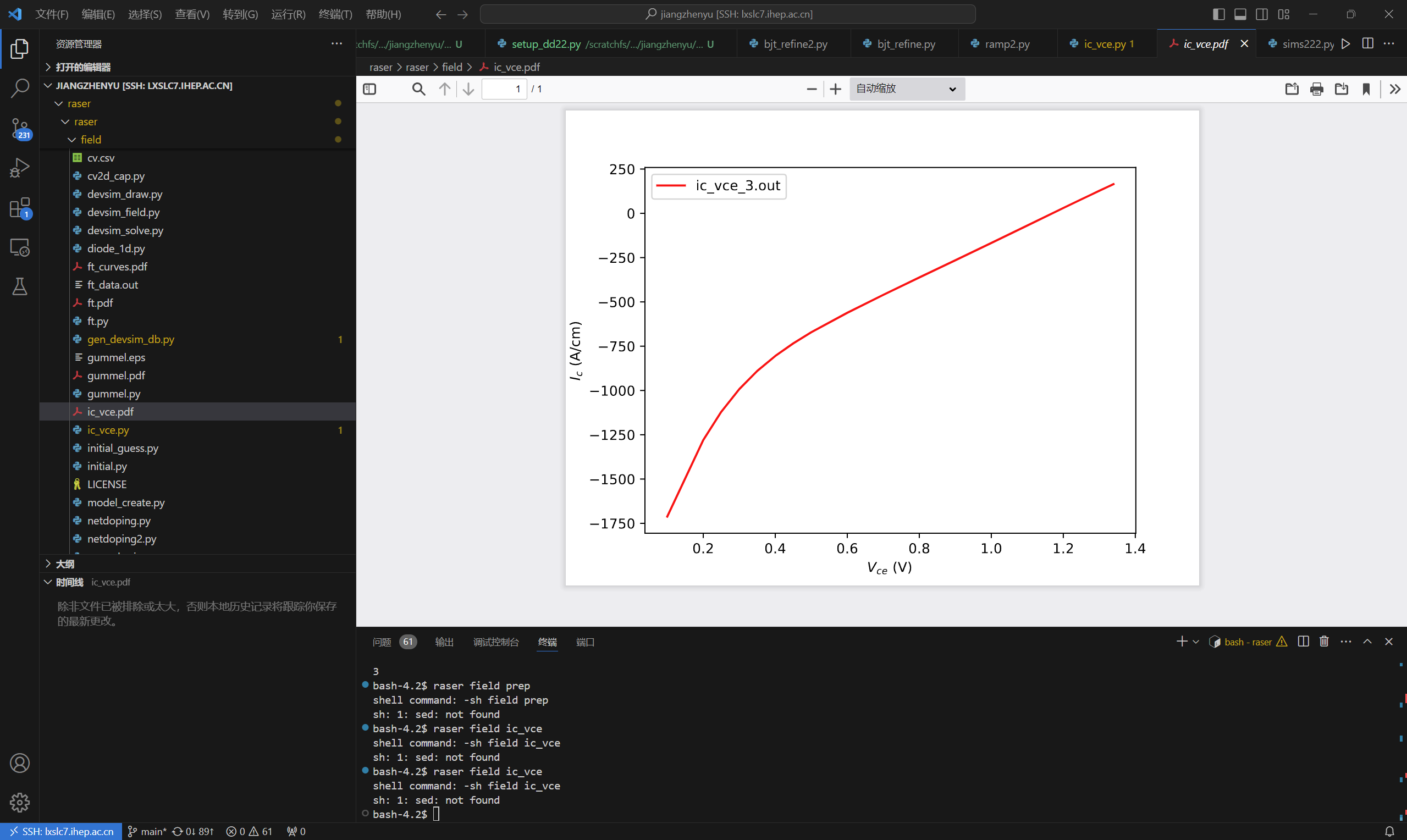


If Vb >> Vc, then Ic will be negative, since the diode is forward biased.
As Vc approaches Vb, then Ic will be reduced.
Note that the bandgap of Silicon is only 1.12 electron volt. So a Vbe of 3 Volts may result in a non physical result.
Hello,author:
Thanks again for your patience and help.
I would like to ask how many times the grid needs to be refined before it is considered complete and what are the criteria for completion.

I don’t know. It depends on this problem. If it is overrefined, then this can cause problems with the mesher and there may be too many nodes to achieve a practical simulation.
The refinement for the BJT example is at only the initial bias step. It may be better to have a different mesh for different ranges of bias. For example, using a different mesh for each V_{CE}.
The refinement scripts in this directory use different refinement criteria.
https://github.com/devsim/devsim_misc/tree/main/refinement
One approach is where the background mesh is calculated over a range of bias points which may be useful if the active regions of the devices are moving around with bias.
https://github.com/devsim/devsim_misc/blob/main/refinement/mos2d_refine2.py
Hello author:
It’s been a while since I’ve been in touch with you, I don’t know if you remember me.
Regarding the simulation of the 4H-SiC BJT I don’t think it’s finished yet, the difference between the results I got from the commercial software and the devsim simulation is very big, the devsim simulation has a gain of more than 1000 times, while the commercial software has only 10 or so times.
I’ve uploaded my code and results on github, could you please take a look at it sometime to see if there are any errors?I think there must be a very obvious problem, but I can’t find it.
Thanks again for your patience! ![]()
I tried your example again and found that the gain given in your example is also very different from the gain I simulated with silvaco.Do you know what causes this difference?
I tried a lot of voltages and found that I couldn’t match them anyhow
If you don’t see a problem with my code, I’ll look into the reasons for this difference next.
In 2D, the assumed unit of contact current is A/cm since the third dimension is not known. This is since the models in devsim assume the units are in cm for the mesh and device parameters. Please check what unit the other simulator is using when reporting current.
For example, please see this discussion:
https://www.researchgate.net/post/What_are_the_units_of_current_which_Silvaco_ATLAS_uses_by_default_when_calculating_the_current_using_solve_statement